¶ Tapping Into CAN Bus for a Light Bar Trigger
Vehicle used: 2020 Ford Explorer Limited
Goal: Automatically trigger an auxiliary light bar from the factory high beam state using CAN bus data.
Status: Working proof-of-concept using Arduino + MCP2515 + MOSFET relay control.
¶ Overview
The goal of this project was to control an auxiliary light bar on a 2020+ Ford Explorer using the vehicle’s factory high beam signal.
A physical switch could have been used, but that would have been less convenient and less integrated. The cleaner solution was to detect the high beam state from the vehicle’s CAN bus and use that signal to automatically activate or deactivate the light bar.
On this Explorer, the headlight assembly does not expose a simple high beam positive or ground trigger. The switching is handled internally through vehicle modules, and the useful high beam state is communicated electronically over CAN.
To solve this, the project used:
- An Arduino for logic
- An MCP2515 CAN bus module for CAN communication
- A MOSFET circuit to control the relay ground
- A buck converter to safely power the electronics from vehicle voltage
- A light bar relay harness modified so the relay coil is controlled by the Arduino circuit
The finished setup listens to CAN traffic, identifies the high beam message, and switches the light bar relay when the high beams are on.
¶ Safety Notes
This project involves tapping into vehicle CAN wiring and modifying auxiliary lighting control circuits.
Proceed carefully.
- Do not transmit onto the CAN bus unless you fully understand what you are doing.
- Use listen-only behavior wherever possible during discovery.
- Verify all wiring against your own vehicle’s wiring diagrams.
- Do not assume pinouts are identical across trims, years, or platforms.
- Fuse any power feeds appropriately.
- Protect the microcontroller from automotive voltage spikes and noise.
- Keep the light bar’s main power path separate from the Arduino control circuit.
- Understand your local laws regarding auxiliary lighting tied to high beams.
¶ Parts Used
¶ Control Electronics
- Arduino-compatible microcontroller
- MCP2515 CAN bus module
- LM2596 buck converter
- IRL540N logic-level MOSFET
- 220 Ω resistor for MOSFET gate
- 10 kΩ resistor between MOSFET gate and source
- 1N4007 flyback diode across the relay coil
- 220 µF capacitor on buck converter input
- 0.1 µF capacitor on buck converter output
- PCB or prototyping board
- Enclosure for finished circuit
¶ Vehicle / Lighting Side
- Auxiliary light bar
- Light bar relay harness
- Existing or added switch if manual override is desired
- Appropriate wire, terminals, heat shrink, loom, and protection
- Properly sized fuse for the light bar power circuit
¶ Why CAN Bus Was Needed
The first attempt was to probe the headlight wiring directly and look for a high beam trigger.
That did not work.
The 2020+ Explorer does not appear to expose a convenient high beam positive or ground signal at the headlight wiring. The high beam state is controlled through the vehicle’s electronic modules rather than a simple switched wire.
The next attempt was to read the signal through the OBD-II port. That also did not work for this use case.
The OBD-II port was not providing the continuous, real-time high beam status needed for this project. The relevant signal had to be captured by directly accessing the CAN bus.
¶ CAN Bus Access Point
The useful CAN traffic was accessed from the HS2 CAN bus at the C140 joint connector.
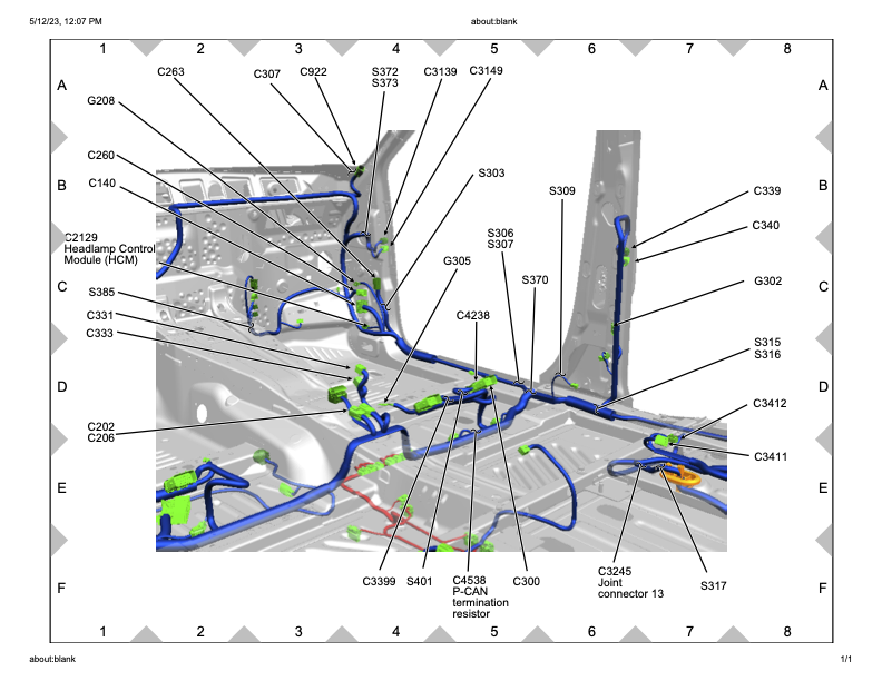
The C140 connector is accessible from the passenger-side trim area.
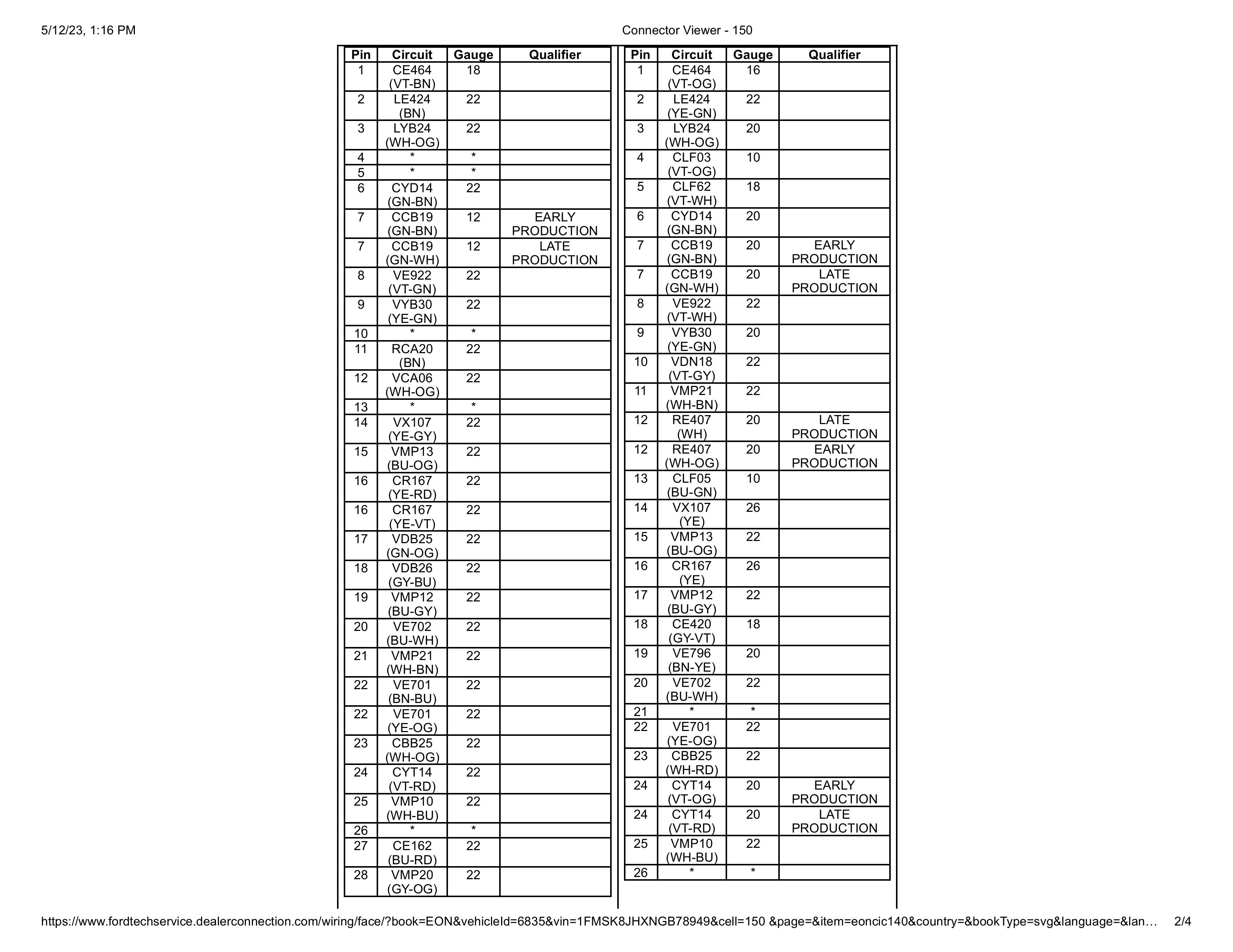
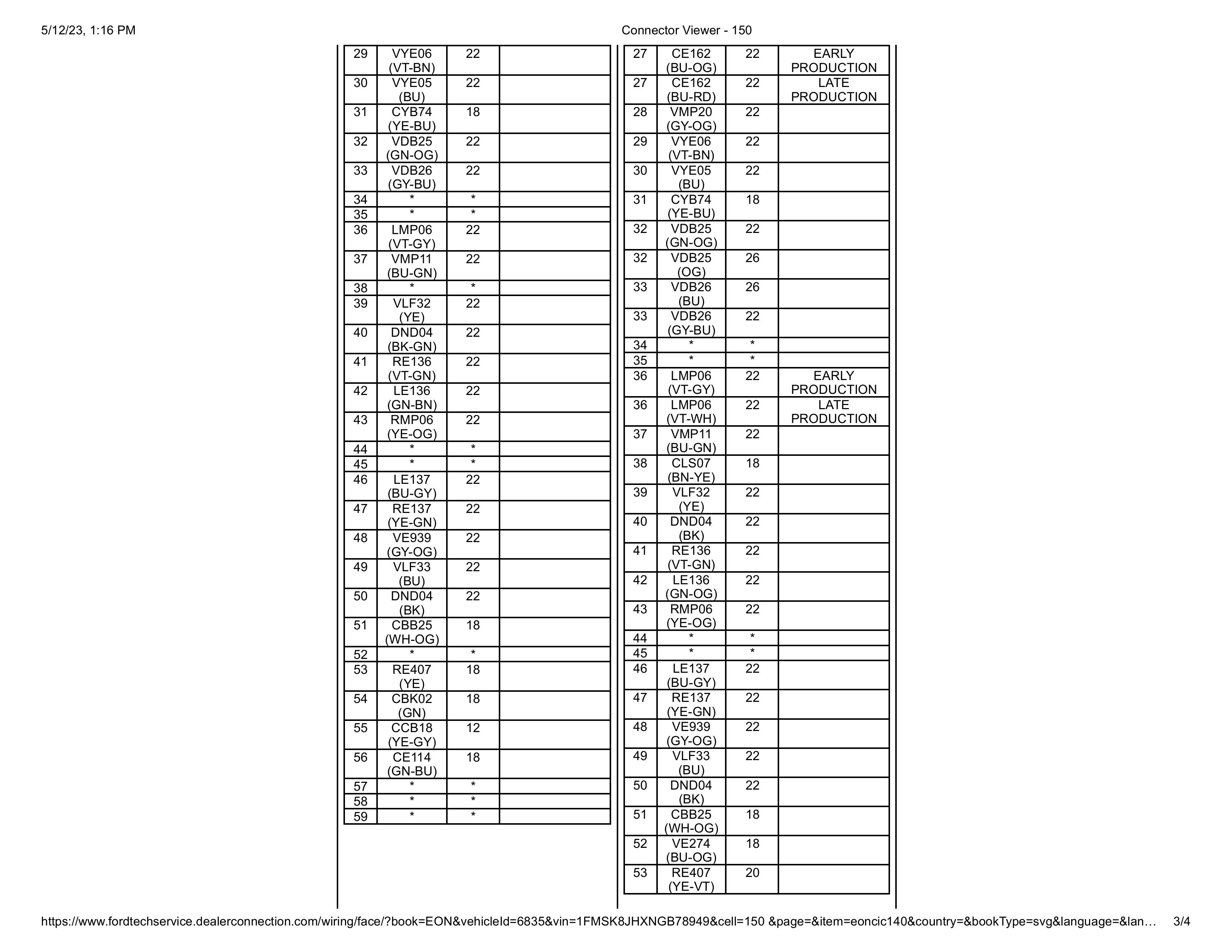
For this specific vehicle, the relevant wiring was:
| Function | Circuit | Pin |
|---|---|---|
| CAN High | VDB25 | Pin 17 |
| CAN Low | VDB26 | Pin 18 |
| Power Source | CBB25 | Pin 51 |
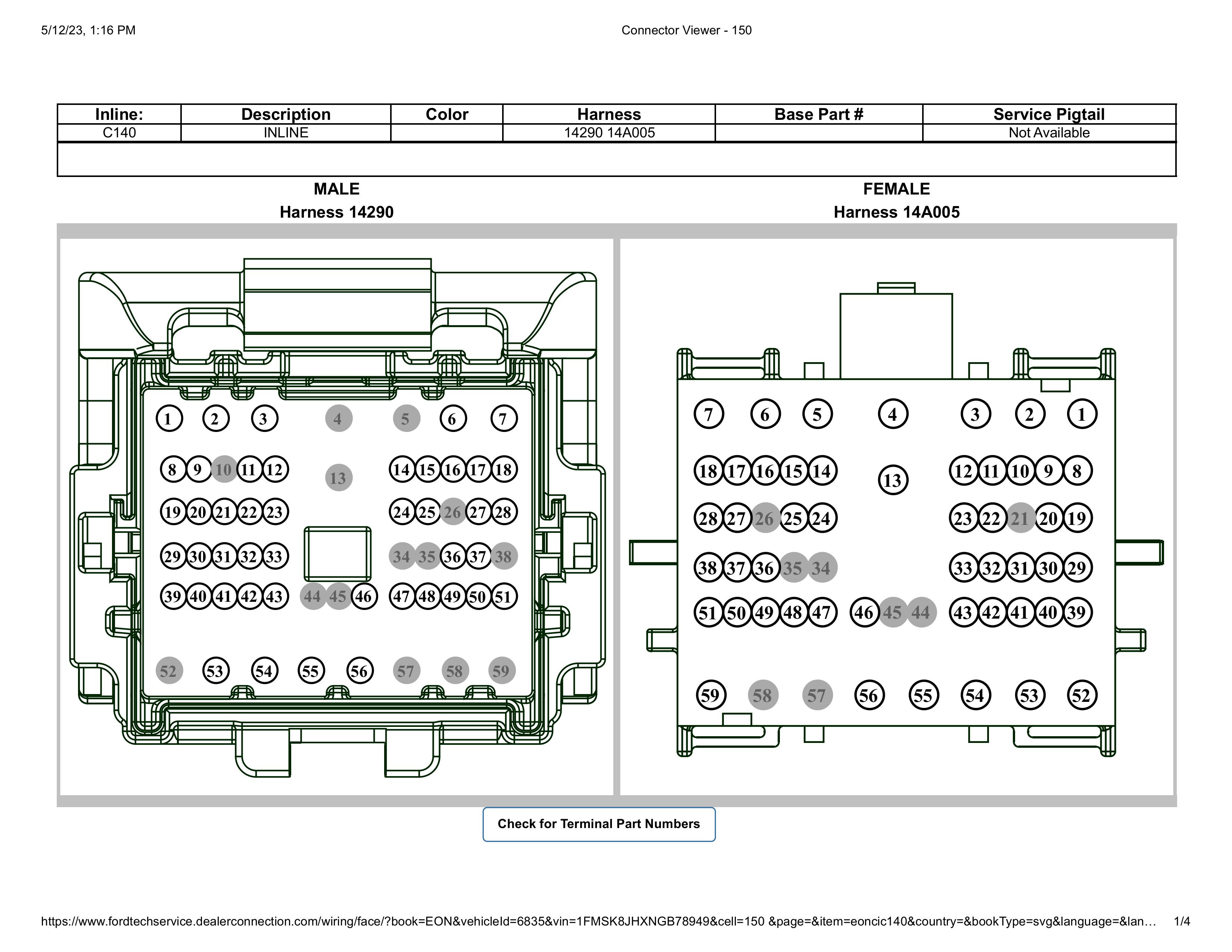
The CAN pair can usually be identified as a twisted wire pair. Twisted pairs are used because CAN is a differential communication system. Twisting the wires helps reject electromagnetic interference by causing noise to affect both wires similarly, allowing the receiver to cancel it out.
Important: Verify your own wiring diagrams. These pins worked for this specific 2020 Explorer Limited, but they may not be universal across every model year, trim, or configuration.
¶ Signal Discovery
Once connected to the HS2 CAN wires, the Arduino and MCP2515 were able to sniff CAN traffic.
The first issue was volume.
There is a lot of CAN traffic, and printing everything in raw hexadecimal made it harder to visually isolate the useful signal. Converting the data output to decimal made it easier to compare repeated message patterns while toggling the high beams.
The relevant high beam messages were found on CAN ID 131, which is 0x83 in hexadecimal.
¶ Identified High Beam Messages
| State | CAN ID | Data |
|---|---|---|
| Holding brights / stalk interaction | 131 | 64 32 0 0 12 150 0 0 |
| Brights ON | 131 | 128 32 0 0 4 148 0 0 |
| Brights OFF | 131 | 0 32 0 0 8 146 0 0 |
The final control logic watches CAN ID 0x83.
The important bytes used in the control code are:
| Byte | Purpose |
|---|---|
buf[4] |
Additional validation byte |
buf[5] |
High beam state byte |
The values used were:
| Meaning | Value |
|---|---|
| Brights OFF | 146 |
| Brights ON | 148 |
| Verify bright state | 4 |
The light bar is only activated when:
buf[4] == 4 && buf[5] == 148
The light bar is turned off when:
buf[5] == 146
¶ Circuit Design
The circuit has four major jobs:
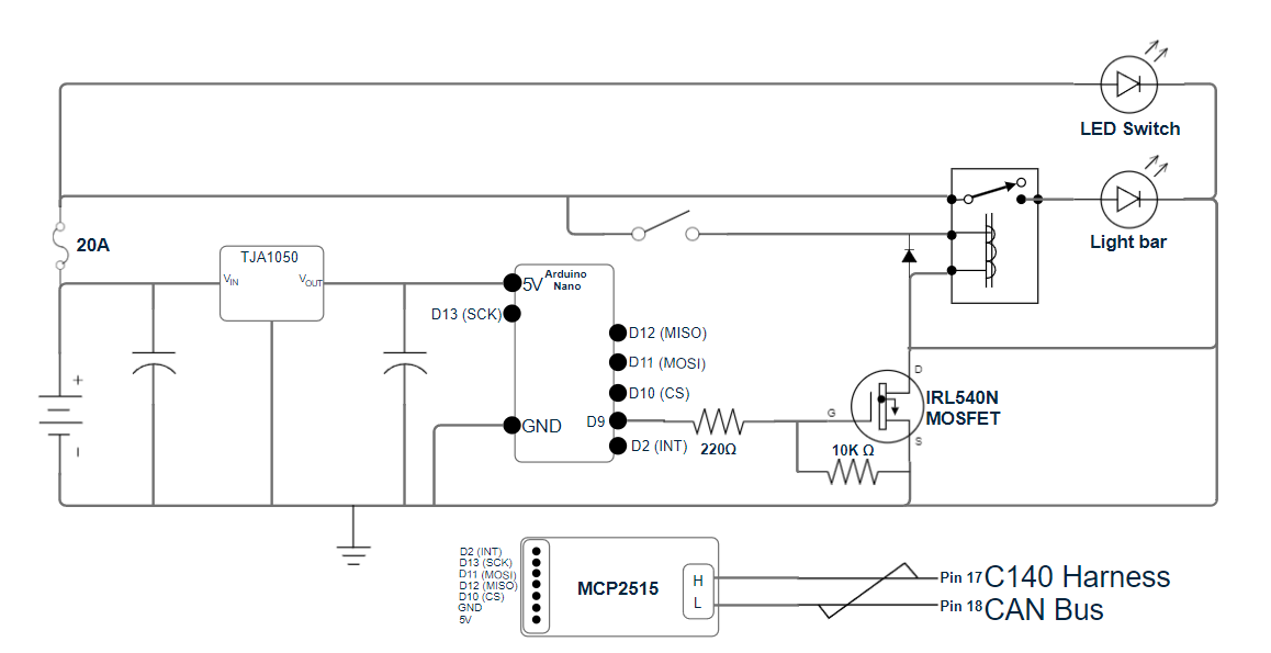
- Step vehicle voltage down to a safe level for the Arduino.
- Allow the Arduino to read CAN bus traffic through the MCP2515.
- Use a MOSFET to control the relay coil ground.
- Protect the Arduino and MOSFET from relay coil voltage spikes.
¶ Power Regulation
Vehicle voltage is not clean enough to feed directly into the Arduino.
The circuit uses an LM2596 buck converter to step vehicle voltage down to a safe voltage for the Arduino and MCP2515.
A 220 µF capacitor was placed on the input side of the buck converter to help smooth voltage fluctuations from the vehicle electrical system.
A 0.1 µF capacitor was placed on the output side of the buck converter to help filter high-frequency noise and stabilize the voltage being supplied to the Arduino.
¶ Arduino to MCP2515 Wiring
The MCP2515 communicates with the Arduino over SPI.
| Arduino Pin | MCP2515 Pin |
|---|---|
| Pin 10 | CS |
| Pin 13 | SCK |
| Pin 11 | SI |
| Pin 12 | SO |
| VCC | VCC |
| GND | GND |
The interrupt pin was originally wired and used in early testing, but it was not needed in the final setup. The main loop checked the high beam state quickly enough that there was no noticeable delay.
¶ MOSFET Relay Control
The Arduino does not directly power the light bar.
Instead, the Arduino controls an IRL540N MOSFET. The MOSFET switches the ground side of the relay coil.
The Arduino output pin connects to the MOSFET gate through a 220 Ω resistor. This limits current into the gate and protects the Arduino output pin.
A 10 kΩ resistor is connected between the MOSFET gate and source. This acts as a pull-down resistor and keeps the MOSFET off when the Arduino is not actively driving the gate.
When the Arduino detects that the high beams are on, it drives the MOSFET gate high. The MOSFET then completes the relay coil ground path, energizing the relay and turning on the light bar.
¶ Relay Harness Ground Modification
The light bar harness was modified so the relay coil and switch indicator ground are routed through the MOSFET.
Originally, the light bar ground, LED switch ground, and relay coil ground shared a common ground path.
The revised setup works like this:
- The light bar’s main ground remains connected directly to the battery or appropriate chassis ground.
- The relay coil ground is routed through the MOSFET drain.
- The LED switch indicator ground is also routed through the MOSFET-controlled side.
This prevents the switch indicator from staying illuminated when the system is off.
It also allows the switch to act as a manual enable/disable control. If the switch breaks the positive side of the relay coil, the factory high beams can still be used without activating the light bar.
¶ Flyback Diode Protection
A relay coil generates a voltage spike when it is de-energized.
To protect the Arduino and MOSFET, a 1N4007 flyback diode was placed across the relay coil in reverse bias.
This gives the relay coil’s collapsing magnetic field a safe discharge path and helps prevent voltage spikes from damaging the MOSFET or microcontroller.
¶ Arduino Code: Signal Discovery
Use this sketch to print CAN messages and help identify useful signals.
This version prints the CAN ID in hexadecimal and the data bytes in decimal.
#include <SPI.h>
#include <mcp_can.h>

MCP_CAN mcp2515(10);  // Set the CS pin for the MCP2515, adjust as necessary

void setup() {
    Serial.begin(115200);  // Start serial communication

    if (mcp2515.begin(MCP_STDEXT, CAN_500KBPS, MCP_8MHZ) == CAN_OK) {
        Serial.println("MCP2515 Initialized Successfully!");
    } else {
        Serial.println("MCP2515 Initialization Failed!");
        while (1);  // Stay in loop if initialization fails
    }

    mcp2515.setMode(MCP_NORMAL);  // Set the MCP2515 to normal mode
}

void loop() {
    // Check if a CAN message is available
    if (mcp2515.checkReceive() == CAN_MSGAVAIL) {
        unsigned char len = 0;  // Length of the received message
        unsigned char buf[8];   // CAN message buffer
        unsigned long id = 0;   // CAN message ID

        // Read the message from the CAN bus
        mcp2515.readMsgBuf(&id, &len, buf);

        // Print the CAN message ID
        Serial.print("CAN ID: ");
        Serial.println(id, HEX);  // Print the CAN ID in hexadecimal

        // Print the data of the message
        Serial.print("Data: ");
        for (int i = 0; i < len; i++) {
            Serial.print(buf[i], DEC);  // Print each byte in decimal
            Serial.print(" ");
        }

        Serial.println();  // Newline after each message
    }
}
¶ Arduino Code: Light Bar Activation
This sketch watches CAN ID 0x83 and switches the light bar control pin based on the high beam state.
#include <SPI.h>
#include <mcp_can.h>

MCP_CAN mcp2515(10);  // Set the CS pin for the MCP2515, adjust this if necessary

const int LIGHTBAR_PIN = 4;           // Pin to control the MOSFET
const unsigned long CAN_ID = 0x83;    // CAN ID 0x83 corresponds to 131 decimal

// Define byte values for bright states
const byte BRIGHT_OFF = 146;    // Brights are off
const byte BRIGHT_ON = 148;     // Brights are on
const byte VERIFY_BRIGHT = 4;   // Additional validation byte

void setup() {
    Serial.begin(115200);  // Start serial communication

    pinMode(LIGHTBAR_PIN, OUTPUT);     // Set the lightbar MOSFET control pin as output
    digitalWrite(LIGHTBAR_PIN, LOW);   // Ensure the lightbar is off at startup

    if (mcp2515.begin(MCP_STDEXT, CAN_500KBPS, MCP_8MHZ) == CAN_OK) {
        Serial.println("MCP2515 Initialized Successfully!");
    } else {
        Serial.println("MCP2515 Initialization Failed!");
        while (1);  // Stay in a loop if initialization fails
    }

    // Set the MCP2515 mode to normal for reading real CAN messages
    mcp2515.setMode(MCP_NORMAL);

    // Set up masks and filters to isolate CAN ID 0x83
    mcp2515.init_Mask(0, 0x7FF);   // Initialize mask 0 for standard 11-bit IDs
    mcp2515.init_Filt(0, CAN_ID);  // Filter for CAN ID 0x83
    mcp2515.init_Filt(1, CAN_ID);  // Second filter for CAN ID 0x83
}

void loop() {
    // Check if a message is available on the CAN bus
    if (mcp2515.checkReceive() == CAN_MSGAVAIL) {
        unsigned char len = 0;  // Length of the received message
        unsigned char buf[8];   // CAN message buffer
        unsigned long id = 0;   // CAN message ID

        // Read the CAN message
        mcp2515.readMsgBuf(&id, &len, buf);

        // Process only the messages that match the filtered ID
        if (id == CAN_ID) {
            // Check if the brights are OFF using the sixth byte
            if (buf[5] == BRIGHT_OFF) {
                Serial.println("Brights are OFF. Turning off the light bar.");
                digitalWrite(LIGHTBAR_PIN, LOW);
            }

            // Check if the brights are ON using validation byte and state byte
            else if (buf[4] == VERIFY_BRIGHT && buf[5] == BRIGHT_ON) {
                Serial.println("Brights are ON. Turning on the light bar.");
                digitalWrite(LIGHTBAR_PIN, HIGH);
            }

            // Print the data for debugging
            Serial.print("Data for ID 131 (0x83): ");
            for (int i = 0; i < len; i++) {
                Serial.print(buf[i], DEC);
                Serial.print(" ");
            }

            Serial.println();
        }
    }
}
¶ Programming Notes
¶ CAN ID
The discovered high beam message used CAN ID 0x83, or 131 decimal.
This may not be the same on every vehicle.
Always verify the CAN ID and byte pattern on your own vehicle before relying on the control logic.
¶ Baud Rate
This setup used:
CAN_500KBPS
If the MCP2515 does not initialize or the messages look wrong, verify the bus speed.
¶ MCP2515 Clock
This setup used:
MCP_8MHZ
Some MCP2515 modules use an 8 MHz crystal, while others use 16 MHz. Match the code to your board.
¶ Serial Printing
Serial printing is useful during discovery, but it can slow down processing when the bus is busy.
Once the system is finalized, remove or minimize serial debug output.
¶ Listen-Only Consideration
During discovery, it is best practice to run the CAN interface in listen-only mode if possible.
The goal is to observe CAN traffic, not transmit onto the bus.
The posted working code uses MCP_NORMAL, but for initial discovery and safety, consider using listen-only mode if your library and setup support it.
¶ Final Enclosure
After the software and circuit were working, the next step was packaging the electronics.
The goal was to build a small enclosure that could fit neatly in the passenger-side footwell area without interfering with existing trim, wiring, or vehicle controls.
The enclosure was designed around the specific PCB dimensions used in this project. If recreating it, the CAD model would likely need to be adjusted for your own board layout, connector placement, and wiring exit paths.
A good enclosure should:
- Secure the PCB
- Protect the electronics from vibration
- Prevent accidental shorts
- Allow service access
- Provide strain relief for wiring
- Fit cleanly behind trim or in the footwell area
- Avoid interference with pedals, airbags, HVAC components, or passenger movement
¶ Troubleshooting
¶ MCP2515 Does Not Initialize
Check:
- CS pin matches the code
- Correct crystal setting:
MCP_8MHZvsMCP_16MHZ - Correct CAN speed
- SPI wiring
- Power and ground
- MCP2515 module voltage compatibility
- CAN High and CAN Low are not reversed
¶ CAN Data Is Garbled or Missing
Check:
- Correct CAN bus pair
- Correct baud rate
- Good ground reference
- CAN High / CAN Low polarity
- Loose taps or poor connector contact
- MCP2515 clock setting
- Whether the bus is active only with ignition on
¶ Light Bar Does Not Turn On
Check:
- Arduino output pin matches
LIGHTBAR_PIN - MOSFET orientation
- Gate resistor wiring
- 10 kΩ pull-down resistor placement
- Relay coil wiring
- Relay coil positive feed
- MOSFET ground path
- Flyback diode orientation
- Light bar relay harness fuse
- Manual switch state, if retained
¶ Light Bar Stays On
Check:
- MOSFET gate is not floating
- 10 kΩ gate-to-source resistor is installed
- Arduino pin is set LOW at startup
- Relay coil ground is only completed through the MOSFET
- The high beam OFF message is being detected
- CAN byte values match your vehicle
¶ Switch Indicator Stays Lit
Check:
- LED switch indicator ground routing
- Relay coil ground routing
- Whether the LED indicator still has a constant ground path
- Whether the switch positive side is wired as intended
¶ Lessons Learned
The biggest lesson from this project is that modern vehicle lighting circuits may not expose simple trigger wires anymore.
The high beam state existed, but it was not available as a basic switched wire at the headlight assembly. It had to be read from the vehicle network.
The OBD-II port was also not enough for this use case because it did not provide the continuous real-time signal needed to trigger the light bar.
Direct CAN access was the reliable solution.
Once the correct CAN message was isolated, the rest of the system became straightforward:
- Read CAN message.
- Validate high beam state.
- Drive MOSFET.
- Energize relay.
- Turn on light bar.
¶ Future Ideas
This same general approach could be expanded beyond light bar control.
Possible future uses:
- Auto-enable Sport mode on startup
- Disable auto stop-start behavior
- Trigger accessories based on vehicle state
- Add custom indicators
- Build configurable vehicle behavior modules
- Create a more polished PCB revision
- Add a service/programming port
- Add status LEDs for power, CAN activity, and output state
¶ Summary
This project successfully used an Arduino and MCP2515 CAN bus module to monitor the high beam state on a 2020 Ford Explorer and automatically control an auxiliary light bar.
The key working signal was:
CAN ID: 0x83 / 131 decimal

Brights ON:
128 32 0 0 4 148 0 0

Brights OFF:
0 32 0 0 8 146 0 0
The Arduino watches for that message, verifies the high beam state, and drives a MOSFET that completes the relay coil ground path for the light bar harness.
The result is an integrated light bar trigger that follows the factory high beams without needing to run a separate physical high beam trigger wire.